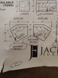
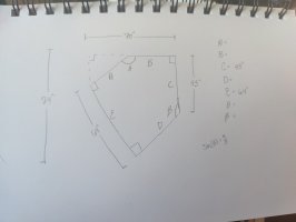
I'm planning on buying a new couch, but I am wanting to map out in my living room to see how it would fit first. There's one odd shaped piece where the manufacturer did not provide all the length measurements. From what I can tell, there's not enough information to find the three missing lengths and the two missing angles. If there is, I would greatly appreciate an answer or explanation on how to find the missing sides. I have attached images of the manufacturers diagram and my own sketch.
You are using an out of date browser. It may not display this or other websites correctly.
You should upgrade or use an alternative browser.
You should upgrade or use an alternative browser.
Side Lengths
- Thread starter Elelay
- Start date
Dr.Peterson
Elite Member
- Joined
- Nov 12, 2017
- Messages
- 16,113
I would probably just measure their picture and scale it as needed for your map, trusting the (approximate) accuracy of the picture. I assumed there is not enough information.
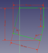
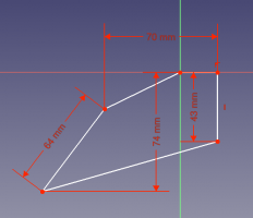
But just for fun, I drew it up on GeoGebra, initially missing the 43 inch measurement and just moving A until it looked right. But I found when I made the angle match the picture, the 43 was wrong:

To get the 43" right, we need this angle:

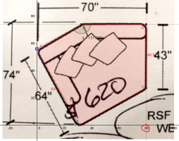
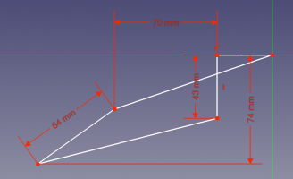
My next step would have been to calculate everything properly; but it looks like the data are actually inconsistent with the drawing. It's possible, I suppose, that their measures at curved corners could account for some of the error. Looking at the dimensions of the drawing, the 70" width is more like 80:
 That doesn't quite work, but it's closer.
But just for fun, I drew it up on GeoGebra, initially missing the 43 inch measurement and just moving A until it looked right. But I found when I made the angle match the picture, the 43 was wrong:
To get the 43" right, we need this angle:
My next step would have been to calculate everything properly; but it looks like the data are actually inconsistent with the drawing. It's possible, I suppose, that their measures at curved corners could account for some of the error. Looking at the dimensions of the drawing, the 70" width is more like 80:
Attachments
blamocur
Elite Member
- Joined
- Oct 30, 2021
- Messages
- 2,641
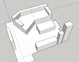
There is not enough data to figure out the angles. Even assuming that the upper left corner has 90 degrees angle you still have 2 degrees of freedom left when only 4 sizes are specified. Just for laughs, I've plotted a pentagon with the specified constraints in FreeCAD, and it allowed all kinds of strange shapes, like the ones attached.
I think @Dr.Peterson's suggestion is your best bet.
I think @Dr.Peterson's suggestion is your best bet.
Attachments
I appreciate both of your quick responses. I'm thinking this is the most accurate I'm going to be able to get it, but still very helpful to give me a good idea on how it will fit. (plus, the confirmations that I haven't forgotten how to do geometry and that there just isn't enough data) Thank you both!
Attachments
Dr.Peterson
Elite Member
- Joined
- Nov 12, 2017
- Messages
- 16,113
You're ignoring two other implied right angles in the figure (A, B, and D). Include them all, and the solution is possible; I get a quadric equation that puts B at x=61.94, agreeing with my second image. Change the 70 to 80 and I get 38.02, as in my third.There is not enough data to figure out the angles. Even assuming that the upper left corner has 90 degrees angle you still have 2 degrees of freedom left when only 4 sizes are specified. Just for laughs, I've plotted a pentagon with the specified constraints in FreeCAD, and it allowed all kinds of strange shapes, like the ones attached.
I think @Dr.Peterson's suggestion is your best bet.
blamocur
Elite Member
- Joined
- Oct 30, 2021
- Messages
- 2,641
Yeah, with two more right angles the thing is fully constrained, but FreeCAD gave me the same shape (attached) as the one you've posted earlier. On the other hand, we both use polygons whereas the original post shows rounded corners.You're ignoring two other implied right angles in the figure (A, B, and D). Include them all, and the solution is possible; I get a quadric equation that puts B at x=61.94, agreeing with my second image. Change the 70 to 80 and I get 38.02, as in my third.