Hello,
I'm new here! Please forgive me if I've posted this in the wrong category. I'm not sure exactly where this should be other than this one.
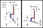
I have a question that's been driving me nuts for quite some time. I have posted a diagram showing a linkage with limited movement. Looking at the diagram, I need to figure out the angle of "Part 2" and "Part 3" for any given distance between 656.258199 and 1110.
Here's the problem:
"Part 1" can ONLY move up and down and the green pivot point at side b and c of "Part 3" can ONLY move up and down. It cannot move back and forth. The red vertical line can be considered a piston that is connected at the pivot point of sides b and c of "Part 3" and extends up inside "Part 1".
The very bottom line in the diagram can be considered a ground line.
The first frame of the illustration shows the linkage at full extension and the second shows the linkage at full compression. "Part 2" starts at sweep angle 0 and at full compression sits at 11.49746749 degrees through an arc of radius = 400.
Side "a" of "Part 3" sits @ 50.75456535 degrees and at full compression is decreased exactly 34 degrees for a resultant angle of 16.75456535 degrees.
I can figure every thing else out if I take an arbitrary sweep angle between 0 and 34 for "Part 3". The problem I have is taking ONLY the vertical distance traveled by "Part 1" and extrapolating the rest from that. I've come very, very close. I just can't seem to figure out the formula though. I know it's possible. Please help me, I'm going crazy. I think I've gone through half a ream of paper working on this and for some reason I'm missing it.
Sincerely,
Cliff
I'm new here! Please forgive me if I've posted this in the wrong category. I'm not sure exactly where this should be other than this one.
I have a question that's been driving me nuts for quite some time. I have posted a diagram showing a linkage with limited movement. Looking at the diagram, I need to figure out the angle of "Part 2" and "Part 3" for any given distance between 656.258199 and 1110.
Here's the problem:
"Part 1" can ONLY move up and down and the green pivot point at side b and c of "Part 3" can ONLY move up and down. It cannot move back and forth. The red vertical line can be considered a piston that is connected at the pivot point of sides b and c of "Part 3" and extends up inside "Part 1".
The very bottom line in the diagram can be considered a ground line.
The first frame of the illustration shows the linkage at full extension and the second shows the linkage at full compression. "Part 2" starts at sweep angle 0 and at full compression sits at 11.49746749 degrees through an arc of radius = 400.
Side "a" of "Part 3" sits @ 50.75456535 degrees and at full compression is decreased exactly 34 degrees for a resultant angle of 16.75456535 degrees.
I can figure every thing else out if I take an arbitrary sweep angle between 0 and 34 for "Part 3". The problem I have is taking ONLY the vertical distance traveled by "Part 1" and extrapolating the rest from that. I've come very, very close. I just can't seem to figure out the formula though. I know it's possible. Please help me, I'm going crazy. I think I've gone through half a ream of paper working on this and for some reason I'm missing it.
Sincerely,
Cliff