You are using an out of date browser. It may not display this or other websites correctly.
You should upgrade or use an alternative browser.
You should upgrade or use an alternative browser.
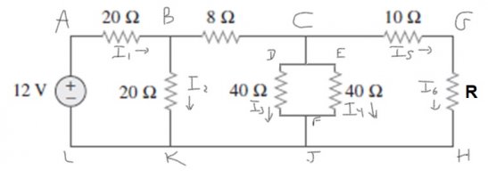
Consider the circuit shown in the figure.
- Thread starter Scaletta
- Start date

topsquark
Senior Member
- Joined
- Aug 27, 2012
- Messages
- 2,363
Okay. I have to check first. Are you using Kirchoff's rules or are you simplifying resistors? And I presume [imath]R = 0 ~ \Omega[/imath] is the internal resistance of the source?
I have loaded a new image with some annotations for discussion. The capital letters indicate the corner locations.
-Dan
I have loaded a new image with some annotations for discussion. The capital letters indicate the corner locations.
-Dan
Attachments
Hello, thank you for replying.
I am using Kirchhoff rules, however at certain times I also simplify resistors. Regarding the internal resistance of the source, it is not given by the problem statement, so it is an unknown value. Is it necessary to know that value to solve the problem?
I am using Kirchhoff rules, however at certain times I also simplify resistors. Regarding the internal resistance of the source, it is not given by the problem statement, so it is an unknown value. Is it necessary to know that value to solve the problem?
Okay. I have to check first. Are you using Kirchoff's rules or are you simplifying resistors? And I presume [imath]R = 0 ~ \Omega[/imath] is the internal resistance of the source?
I have loaded a new image with some annotations for discussion. The capital letters indicate the corner locations.
-Dan
topsquark
Senior Member
- Joined
- Aug 27, 2012
- Messages
- 2,363
No. If an internal resistance is not specified we usually just assume its [imath]0 ~ \Omega[/imath]. Sometimes in real circuit diagrams a small resistor is listed on the diagram to represent it.Hello, thank you for replying.
I am using Kirchhoff rules, however at certain times I also simplify resistors. Regarding the internal resistance of the source, it is not given by the problem statement, so it is an unknown value. Is it necessary to know that value to solve the problem?
I see now, though. Apparently they are telling you to ignore the resistor on the far right.
First: I forgot to list a current in the [imath]8 ~ \Omega[/imath] resistor so let's call that [imath]I_6[/imath] seeing as the R resistor doesn't actually exist.
Second: We are going to need a new current and a new node point. Call [imath]I_7[/imath] the current coming down out of the C node, and I am going to label M the point on the line DE that this current flows into.
What do we need? [imath]I_4[/imath], [imath]P = I_1 V[/imath], and [imath]I_6[/imath].
Frankly we are probably going to have to solve the whole mess. At least until we set up the system I can't see how to avoid it.
Options:
1) We can write a bunch of current relationships from the points B, C, and M. What are these?
2) Loop rules: As an example, how do you write the equation for the loop ABKLA?
If you are beyond this point please post what your equations (and the loops they came from, please!) and we'll go from there.
-Dan
D
Deleted member 4993
Guest
What are the equations that you have derived using Kirchoff's Law?Hello, thank you for replying.
I am using Kirchhoff rules, however at certain times I also simplify resistors. Regarding the internal resistance of the source, it is not given by the problem statement, so it is an unknown value. Is it necessary to know that value to solve the problem?