I have a real-world application Fourier series issue that (I think) is either due to or the solution for my problem.
Background:
I have a set of absolute position, linear encoders that, through O-scope testing and data runs, I’ve found the data Word output from these scales to be 3 pure binary encoded tracks. The readhead output is a 25-bit word that is a combination of the 3 binary track values transmitted LSB first.
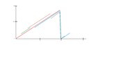
The 3 tracks, hence referred to as Coarse, Mid, & Fine, are 8-bit, 8-bit, & 9-bit length. When graphed, the binary values of each track form 3 sawtooth wave patterns such that one complete cycle of the Coarse track is 16 cycles of the Mid track, and 512 cycles of the Fine track.
As far as I can tell, the Mid track is offset from the other 2 and is most likely just used for noise correction of the other 2 tracks with the final output position being just a combination of the Coarse and Fine track values. In total, this equates to 131,072 possible unique position ID’s over the max possible encoder length.
Each encoder doesn’t necessarily start out at the “Zero” binary position and can be of any length up to the maximum possible before a repeat happens making the positions Absolute.
Issue:
My problem is trying to find the correct equation that will linearize across the Fourier series “Jump”.
If the values are treated as Signed integers, there is a jump from max positive value to max negative value (or vice-versa when traveling in the opposite direction) causing a large jump in position at the point where the Coarse track value goes from positive to negative or 01111111 (127) to 10000000 (128) in binary.
If treated as a Unsigned integer, the same jump happens, but 180 degrees out when Coarse track binary value goes from 11111111 to 00000000.
Since both of these points can and do reside on a single encoder, coding each one separately to be either Signed or Unsigned won’t work.
I apologize if this question should reside elsewhere other than Calculus, but I thought since the signals are a Fourier sawtooth series, it belonged here.
Background:
I have a set of absolute position, linear encoders that, through O-scope testing and data runs, I’ve found the data Word output from these scales to be 3 pure binary encoded tracks. The readhead output is a 25-bit word that is a combination of the 3 binary track values transmitted LSB first.
The 3 tracks, hence referred to as Coarse, Mid, & Fine, are 8-bit, 8-bit, & 9-bit length. When graphed, the binary values of each track form 3 sawtooth wave patterns such that one complete cycle of the Coarse track is 16 cycles of the Mid track, and 512 cycles of the Fine track.
As far as I can tell, the Mid track is offset from the other 2 and is most likely just used for noise correction of the other 2 tracks with the final output position being just a combination of the Coarse and Fine track values. In total, this equates to 131,072 possible unique position ID’s over the max possible encoder length.
Each encoder doesn’t necessarily start out at the “Zero” binary position and can be of any length up to the maximum possible before a repeat happens making the positions Absolute.
Issue:
My problem is trying to find the correct equation that will linearize across the Fourier series “Jump”.
If the values are treated as Signed integers, there is a jump from max positive value to max negative value (or vice-versa when traveling in the opposite direction) causing a large jump in position at the point where the Coarse track value goes from positive to negative or 01111111 (127) to 10000000 (128) in binary.
If treated as a Unsigned integer, the same jump happens, but 180 degrees out when Coarse track binary value goes from 11111111 to 00000000.
Since both of these points can and do reside on a single encoder, coding each one separately to be either Signed or Unsigned won’t work.
I apologize if this question should reside elsewhere other than Calculus, but I thought since the signals are a Fourier sawtooth series, it belonged here.