
Ohm's Law and Simple Circuits
In any simple electric circuit — a battery, a resistor, some wires — three quantities show up everywhere: voltage, current, and resistance. Ohm's law is the single equation that ties them together, and it's the foundation of nearly every circuit analysis you'll do in introductory physics.
The Three Quantities
Voltage \(V\), measured in volts (V), is the electrical "push" — the energy per unit of charge supplied by a source like a battery. A useful analogy is water pressure in a pipe: voltage is what drives the current.
Current \(I\), measured in amperes or amps (A), is the rate at which electric charge flows. One amp means one coulomb of charge passes a point every second. In the water analogy, it's the flow rate.
Resistance \(R\), measured in ohms (Ω, the Greek letter omega), is how much the material resists the flow. A high-resistance material limits current; a low-resistance one lets it through easily. Wires have very low resistance; the filament of an incandescent bulb has a much higher resistance, which is why it heats up enough to glow.
The Equation
Ohm's law says:
\[V = IR\]
Voltage equals current times resistance. With this single equation and basic algebra, you can solve for any one of the three quantities if you know the other two:
| To find | Use |
|---|---|
| Voltage | \(V = IR\) |
| Current | \(I = V / R\) |
| Resistance | \(R = V / I\) |
This is a literal equation — one formula with three letters — and rearranging it is exactly the kind of move covered in solving literal equations.
Worked Example: simple circuit
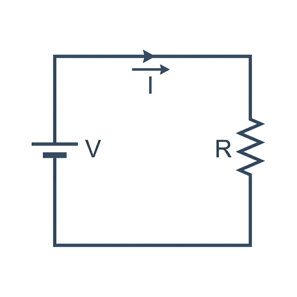
A 9-volt battery drives a current of \(0.3\) A through a single resistor. What is the resistance?
You have \(V = 9\) V and \(I = 0.3\) A. Solve for \(R\):
\[R = \dfrac{V}{I} = \dfrac{9}{0.3} = 30 \text{ Ω}\]
The resistor has a resistance of 30 ohms.
Units and Conversions
In Ohm's law, the units have to match. The standard SI units are volts (V), amperes (A), and ohms (Ω). Real-world problems often use prefixed units — millivolts, milliamps, kilohms. Always convert to base units first:
| Unit | In base units |
|---|---|
| 1 mV (millivolt) | 0.001 V |
| 1 mA (milliamp) | 0.001 A |
| 1 kΩ (kilohm) | 1000 Ω |
| 1 MΩ (megohm) | 1,000,000 Ω |
For example, if a problem mentions "a 5 mA current through a 2 kΩ resistor," convert before substituting:
\(I = 0.005\) A, \(R = 2000\) Ω, so \(V = IR = (0.005)(2000) = 10\) V.
Power
The power dissipated by a resistor — the rate at which it converts electrical energy into heat — is:
\[P = V I\]
measured in watts (W). Substituting Ohm's law into the power formula gives two equivalent versions:
\[P = I^2 R = \dfrac{V^2}{R}\]
All three are the same fact written differently. Use whichever uses the variables you already know.
Worked Example: a 60-watt light bulb
A "60 W" light bulb plugged into a 120 V outlet — how much current does it draw, and what's its resistance?
Current from the power formula:
\[I = \dfrac{P}{V} = \dfrac{60}{120} = 0.5 \text{ A}\]
Resistance from Ohm's law:
\[R = \dfrac{V}{I} = \dfrac{120}{0.5} = 240 \text{ Ω}\]
(A real incandescent bulb's filament has a resistance that changes with temperature, but its operating value at full brightness is around 240 Ω.)
Combining Resistors
When a circuit has more than one resistor, the rules depend on how they're wired.
Series
Resistors in series are wired end-to-end, so the same current flows through each. The total resistance is the sum:
\[R_{\text{total}} = R_1 + R_2 + R_3 + \cdots\]
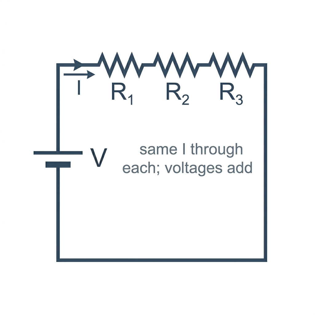
Two 100 Ω resistors in series give a total of 200 Ω. Series wiring always increases the total resistance compared to any single resistor.
Parallel
Resistors in parallel are wired side-by-side between the same two points, so the same voltage is across each. The total resistance is less than the smallest one — current has more paths to choose from, so the effective resistance drops:
\[\dfrac{1}{R_{\text{total}}} = \dfrac{1}{R_1} + \dfrac{1}{R_2} + \cdots\]
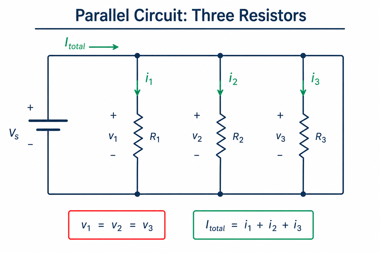
Two 100 Ω resistors in parallel give a total of 50 Ω. Parallel wiring always decreases the total resistance.
Worked Example: combined series and parallel
A 10 V battery is connected to a 4 Ω resistor in series with two parallel 6 Ω resistors. What is the total current the battery supplies?
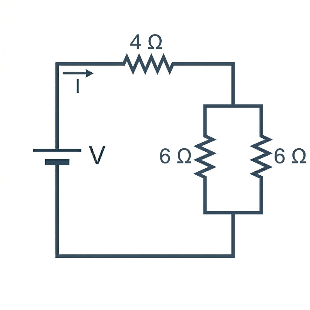
Step 1: combine the two parallel resistors.
\[\dfrac{1}{R_{\text{par}}} = \dfrac{1}{6} + \dfrac{1}{6} = \dfrac{2}{6} = \dfrac{1}{3} \quad \Rightarrow \quad R_{\text{par}} = 3 \text{ Ω}\]
Step 2: add the series resistor.
\[R_{\text{total}} = 4 + 3 = 7 \text{ Ω}\]
Step 3: apply Ohm's law to the whole circuit.
\[I = \dfrac{V}{R_{\text{total}}} = \dfrac{10}{7} \approx 1.43 \text{ A}\]
Practice Problems
1. A current of \(2\) A flows through a 50 Ω resistor. What is the voltage across it? Show answer\(V = IR = (2)(50) = 100\) V.
2. A 12 V battery drives a current of \(0.4\) A. What is the resistance? Show answer\(R = V/I = 12 / 0.4 = 30\) Ω.
3. A device draws \(100\) mA at \(5\) V. How much power does it dissipate? Show answerConvert: \(100\) mA = \(0.1\) A. Power: \(P = VI = (5)(0.1) = 0.5\) W.
4. Three resistors of \(4\) Ω, \(6\) Ω, and \(12\) Ω are wired in parallel. What is the total resistance? Show answer\(\dfrac{1}{R} = \dfrac{1}{4} + \dfrac{1}{6} + \dfrac{1}{12} = \dfrac{3 + 2 + 1}{12} = \dfrac{1}{2}\). So \(R = 2\) Ω.
5. A \(24\) Ω resistor dissipates \(6\) W of power. What current flows through it? Show answerFrom \(P = I^2 R\): \(I = \sqrt{P/R} = \sqrt{6/24} = \sqrt{0.25} = 0.5\) A.
Related Math
Ohm's law is one equation with three variables, plus a power formula and two combination rules. The math you need is mostly:
- Solving Literal Equations — rearranging \(V = IR\) for whichever variable you need
- Solving One-Step Equations — the simplest applications
- Fractions — adding reciprocals for the parallel-resistance formula
For computing values directly, the Ohm's Law Calculator handles any two-of-three case and shows the work.